Important Disclaimer
BatteryStorageHQ provides educational content and estimates only. We are not certified installers, financial advisors, or electricians. Always consult with licensed professionals.
Building Your Own LiFePO4 Battery Bank
Constructing your own lithium iron phosphate (LiFePO4) battery bank offers significant advantages over purchasing pre-built systems. You control every component quality, customize capacity precisely to your needs, and often save considerable money. This comprehensive guide walks you through the entire process from cell selection to final commissioning.
DIY battery building requires attention to detail, respect for electrical safety, and willingness to learn. The satisfaction of powering your home, RV, or off-grid cabin with a system you built yourself is unmatched. More importantly, understanding every component enables better troubleshooting and system optimization throughout the battery’s lifespan.
Understanding LiFePO4 Cell Basics
Cell Types and Formats
LiFePO4 cells come in several formats:
- Prismatic cells: Rectangular aluminum or plastic cases. Common sizes range from 20Ah to 280Ah. Easiest to work with for DIY builds due to convenient terminals and mounting options.
- Cylindrical cells: Similar to AA batteries but larger (18650, 26650, 32650 formats). Often used in power tools and electric vehicles. Require spot welding for proper connections.
- Pouch cells: Flexible polymer pouches. High energy density but require careful handling and compression frames to prevent swelling.
For first-time builders, prismatic cells offer the best balance of capacity, ease of assembly, and reliability. They typically feature M6 or M8 threaded terminals allowing bolted connections without welding.
Nominal Voltage and Capacity
Individual LiFePO4 cells have a nominal voltage of 3.2 volts. Fully charged, they reach 3.6-3.65V. Fully discharged, they drop to approximately 2.5V. This voltage range is significantly safer than other lithium chemistries that operate at higher voltages.
Cell capacity is measured in amp-hours (Ah). A 100Ah cell provides 100 amps for one hour, or 10 amps for ten hours. To calculate energy storage in watt-hours (Wh), multiply amp-hours by voltage: 100Ah × 3.2V = 320Wh per cell.
Properly sizing your battery bank begins with understanding how many cells you need in series and parallel to achieve your desired voltage and capacity.
Cell Grades and Quality
Not all cells are created equal. Cell grades indicate quality levels:
- Grade A: Highest quality, matched capacity, consistent internal resistance. Best for automotive and critical applications. Premium pricing.
- Grade B: Slightly varying capacity and resistance. Excellent for DIY energy storage where minor imbalances are manageable. Best value for most builders.
- Grade C: Significant variation, potential defects. Avoid for battery banks requiring reliability.
Reputable manufacturers include EVE, CATL, Lishen, and BYD. Avoid unknown brands selling suspiciously cheap cells, which often have inflated capacity ratings and safety issues.
Tools and Materials Needed
Essential Tools
- High-quality torque wrench (for terminal connections)
- Digital multimeter (for voltage and resistance measurements)
- DC clamp meter (for current measurements)
- Wire cutters and strippers
- Crimper for battery cable lugs
- Insulated tools (screwdrivers, wrenches)
- Heat gun (for heat shrink tubing)
Materials and Components
- LiFePO4 cells (number depends on desired voltage and capacity)
- Battery Management System (BMS) rated for your pack voltage and current
- Bus bars or copper bar stock for cell connections
- High-quality battery cable (sized for your current loads)
- Copper lugs and crimp connectors
- Heat shrink tubing (various sizes)
- Cell holders or mounting brackets
- Enclosure or battery box
- Fuses and fuse holders
- Terminal covers and insulation
- Bolts, washers, and nuts (stainless steel preferred)
Safety Equipment
- Safety glasses
- Insulated gloves
- Fire extinguisher (Class D for lithium fires)
- First aid kit
Step 1: Cell Testing and Selection
Initial Inspection
Upon receiving cells, inspect each one carefully:
- Check for physical damage (dents, punctures, swelling)
- Verify terminal condition (clean, undamaged)
- Measure initial voltage (should be 3.2-3.3V for new cells)
- Record cell serial numbers and manufacturer information
- Check manufacturing dates (avoid cells over 6 months old if possible)
Reject any cells showing voltage below 2.5V or above 3.65V, physical damage, or signs of previous use.
Capacity Testing
Professional capacity testing requires specialized equipment, but DIY builders can perform basic validation:
- Charge all cells to identical voltage (3.6V)
- Allow them to rest for 24 hours
- Measure voltage again (should remain consistent)
- Discharge at low current (0.1C or less) and track voltage curve
- Compare resting voltages after discharge (tighter grouping indicates better matched cells)
For critical applications, consider having cells professionally tested and matched. Suppliers like Battery Hookup or Current Connected often provide matched cell sets.
Internal Resistance Testing
Cells with similar internal resistance charge and discharge at similar rates. Significant variations cause imbalances during operation. Use a battery analyzer or specialized tester to measure resistance. Group cells with resistance values within 10% of each other.
Step 2: Planning Your Battery Configuration
Series and Parallel Connections
Building a functional battery bank requires combining cells in series and parallel:
- Series connections increase voltage. Four 3.2V cells in series create a 12.8V battery.
- Parallel connections increase capacity. Two 100Ah cells in parallel create 200Ah capacity.
Common configurations:
- 12V system: 4 cells in series (4S) = 12.8V nominal
- 24V system: 8 cells in series (8S) = 25.6V nominal
- 48V system: 16 cells in series (16S) = 51.2V nominal
For increased capacity, create multiple identical strings and connect them in parallel. A 48V system with two parallel strings of 16 cells each (16S2P) doubles capacity while maintaining 48V.
Voltage and Capacity Calculations
Calculate your configuration:
For a 48V, 200Ah battery bank using 280Ah cells:
- Voltage: 16 cells × 3.2V = 51.2V nominal
- To achieve 200Ah, you need less than one cell’s capacity per string
- Use one string of 16 × 280Ah cells = 280Ah @ 51.2V = 14.3 kWh
- This exceeds 200Ah, providing extra capacity
Alternatively, use smaller cells (100Ah) in parallel:
- Two strings of 16 cells each (16S2P)
- Total: 200Ah @ 51.2V = 10.2 kWh
Review your energy requirements carefully to determine optimal configuration.
Step 3: Cell Arrangement and Mounting
Physical Layout
Arrange cells to minimize connection lengths and allow proper BMS installation:
- Group cells by series position (all cell #1s together, all cell #2s together)
- Allow space for BMS mounting
- Plan wiring runs to minimize clutter
- Ensure adequate airflow for cooling
- Position terminals for easy access
Standard prismatic cells are typically 6.5-7cm thick, 17-20cm wide, and 20-22cm tall. Plan your enclosure dimensions accordingly.
Mounting Options
Secure cells firmly to prevent movement:
- Commercial cell holders provide spacing and mounting points
- Custom aluminum or steel frames work well for large banks
- Non-conductive separators prevent cell-to-cell contact
- Compression straps or bolts hold cells in position
Ensure mounting allows for cell swelling (minimal with LiFePO4 but possible) and thermal expansion. Rigid mounting can damage cells over time.
Cell Compression Considerations
Some cell formats benefit from light compression during cycling. Pouch cells particularly need compression frames. Prismatic cells in hard cases typically do not require compression. Check manufacturer specifications for your specific cells.
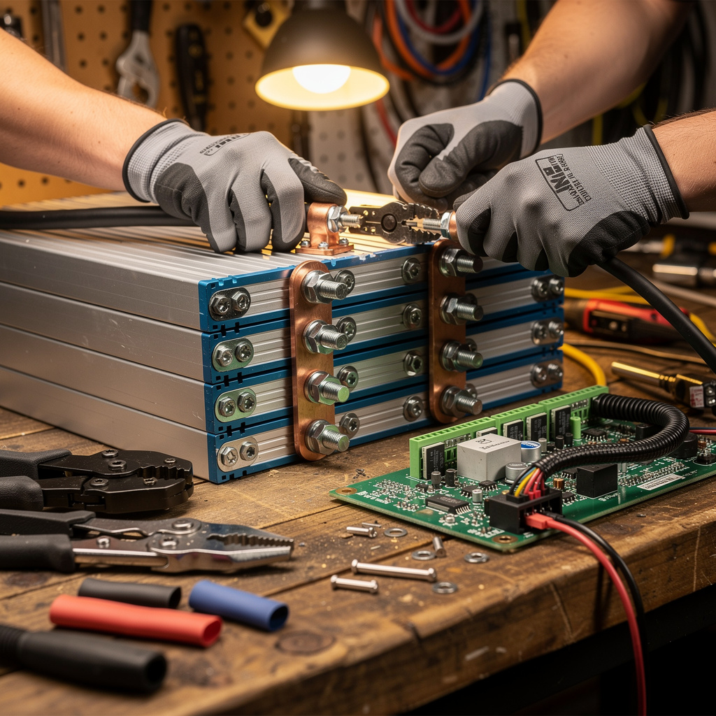
Step 4: Bus Bar Fabrication and Installation
Bus Bar Sizing
Bus bars connect cells in series. Size them for your maximum current with safety margin:
Current capacity by copper bar thickness (at 2A/mm²):
- 3mm × 20mm bar: ~120A continuous
- 3mm × 30mm bar: ~180A continuous
- 5mm × 20mm bar: ~200A continuous
For a 200A battery bank, use 5mm × 30mm or larger bus bars to handle surge currents safely.
Fabrication
Cut copper bar stock to length using a hacksaw or chop saw. Drill holes for cell terminals and connection points. Clean all surfaces with fine sandpaper or a wire brush to ensure good conductivity. Apply no-oxide compound to prevent corrosion.
Installation
Connect bus bars between cell terminals:
- Positive terminal of cell 1 connects to negative terminal of cell 2
- Continue through the series string
- Use Belleville washers or spring washers to maintain torque as connections settle
- Torque to manufacturer specifications (typically 8-12 Nm for M6 bolts)
- Never over-torque, which can damage cell terminals
Use appropriate hardware: stainless steel bolts with washers and lock washers. Nickel-plated copper or brass hardware prevents galvanic corrosion.
Step 5: Battery Management System Installation
BMS Selection
Your Battery Management System is critical for safe operation. Select a BMS rated for:
- Your pack voltage (12V, 24V, or 48V)
- Your maximum continuous current plus 25% margin
- Your maximum surge current
- Number of series cells (4S, 8S, 16S)
- Proper charging and protection parameters
Reputable BMS brands include JK BMS, Daly, JBD, and Overkill Solar. Avoid no-name BMS units which may have poor balancing circuits or inadequate protection.
Balance Wire Installation
Balance wires monitor individual cell voltages and enable balancing:
- Connect BMS balance lead to negative terminal of first cell (most negative)
- Second wire goes to positive terminal of cell 1 / negative terminal of cell 2
- Continue connecting each successive cell junction
- Final wire connects to positive terminal of last cell (most positive)
Double-check every connection before powering the BMS. Reversed connections can damage the BMS or cells.
Main Power Connections
Connect battery main terminals through the BMS:
- Main battery negative connects to BMS B- terminal
- BMS P- terminal becomes your system negative output
- Main battery positive connects directly to system positive (fused appropriately)
Size main power cables for your maximum current with appropriate safety margin. Use high-quality copper lugs crimped properly.
BMS Programming
Configure BMS parameters according to your cell specifications:
- Cell high voltage cutoff (typically 3.65V for LiFePO4)
- Cell low voltage cutoff (typically 2.50V)
- Maximum charge current
- Maximum discharge current
- Balance start voltage (typically 3.40V)
- Temperature protection thresholds
Many modern BMS units offer Bluetooth or WiFi connectivity for monitoring and configuration via smartphone apps.
Step 6: Enclosure Construction
Enclosure Selection
Choose an appropriate enclosure for your battery bank:
- Commercial battery boxes offer convenience but limited customization
- Custom metal enclosures provide durability and flexibility
- Plastic enclosures are lightweight and corrosion-resistant
- Ensure adequate internal volume for cells, BMS, wiring, and airflow
Safety considerations require fire-resistant materials and proper ventilation.
Ventilation and Cooling
LiFePO4 batteries generate heat during high-current charging and discharging. Ensure your enclosure provides:
- Adequate airflow paths
- Cool air intake at bottom
- Hot air exhaust at top
- Fan ventilation for high-current applications
- Temperature monitoring with automatic shutdown at high temperatures
Passive ventilation often suffices for moderate loads. Active cooling with fans improves performance in hot climates or high-power applications.
Wiring Penetrations
Install proper cable glands or feedthroughs for main power cables:
- Use strain relief to prevent cable damage
- Seal penetrations to prevent moisture ingress
- Size penetrations for your cable diameter
- Provide service loops for maintenance access
Step 7: Protection Devices
Overcurrent Protection
Install fuses or circuit breakers to protect against short circuits:
- Main battery fuse rated at 125% of maximum expected current
- Individual fuses for each parallel string (if multiple strings)
- Fuse the positive leg close to the battery terminal
- Use DC-rated fuses or breakers (AC-rated breakers may not properly extinguish DC arcs)
Disconnect Switch
Install a readily accessible disconnect switch for emergency shutdown:
- Rated for your system voltage and current
- Positioned for easy access
- Clearly labeled
- Test regularly to ensure proper operation
Terminal Protection
Cover all exposed terminals to prevent accidental short circuits:
- Use insulated terminal boots
- Install barriers between positive and negative terminals
- Route cables to prevent contact with opposite polarity
- Secure all cables to prevent movement
Step 8: Initial Charging and Testing
First Charge Cycle
Commission your battery bank properly:
- Verify all connections before applying power
- Check BMS settings are correct
- Begin charging at low current (0.1C or less)
- Monitor cell voltages closely during first charge
- Verify BMS balancing function activates as cells reach full charge
- Allow full charge cycle to complete
Initial imbalances are normal and will improve as the BMS balances cells over several cycles.
Capacity Testing
Test your battery bank’s actual capacity:
- Charge to full (3.60-3.65V per cell)
- Discharge at known constant current
- Record time until BMS low voltage cutoff
- Calculate actual capacity: Current (A) × Time (hours) = Ah
Actual capacity should be within 5-10% of rated cell capacity. Significant deviations indicate cell issues or incorrect configuration.
Load Testing
Test your battery under realistic loads:
- Connect actual loads you intend to power
- Verify voltage stability under load
- Check for unexpected heating in connections
- Monitor BMS protection functions
- Test high-current capacity if applicable
Step 9: System Integration
Charging System Connection
Connect your battery to charging sources:
- Solar charge controller output to battery
- AC charger connections
- Alternator charging (for mobile applications)
- Verify charge voltage settings match battery requirements
Proper integration with solar and charging systems ensures optimal performance and longevity.
Inverter Connection
Connect your battery to loads through an inverter:
- Use adequately sized cables for inverter current draw
- Install inverter close to batteries to minimize voltage drop
- Fuse inverter positive line appropriately
- Connect inverter chassis to ground
Monitoring Setup
Implement monitoring for long-term health:
- BMS Bluetooth or WiFi monitoring
- System voltage and current meters
- State of charge indicator
- Cell-level voltage monitoring
Comprehensive monitoring enables proactive maintenance and early problem detection.
Common DIY Battery Building Mistakes
Insufficient Cell Matching
Using poorly matched cells creates imbalance issues. Invest time in testing and matching, or purchase pre-matched sets from reputable suppliers.
Inadequate BMS Protection
Under-rated or poorly programmed BMS units fail to protect cells properly. Use quality BMS units with appropriate ratings and configure correctly.
Improper Torque
Loose connections create resistance and heat. Overtightening damages cell terminals. Use a torque wrench and follow specifications.
Insufficient Fusing
Large battery banks can deliver catastrophic fault currents. Proper fusing protects against catastrophic failures. Size fuses conservatively.
Poor Ventilation
Heat kills batteries. Ensure adequate airflow and monitor temperatures, especially in confined installations.
Long-Term Maintenance
Regular Inspections
Monthly visual inspections catch problems early:
- Check for loose connections
- Verify BMS operation
- Inspect for physical damage
- Monitor cell balance
- Check enclosure integrity
Annual Maintenance
- Retorque all connections
- Clean terminals and bus bars
- Verify BMS calibration
- Test safety devices
- Review and update documentation
Conclusion
Building your own LiFePO4 battery bank is a rewarding project that provides custom energy storage tailored to your specific needs. By following this guide, selecting quality components, and paying attention to detail during assembly, you create a system that rivals commercial offerings at significantly lower cost.
The knowledge gained during construction serves you throughout the battery’s life. Understanding every connection, every parameter, and every protection feature enables effective troubleshooting and optimization. Your DIY battery bank becomes not just a power source, but a testament to self-reliance and technical capability.
Remember that safety remains paramount throughout the build process and operational life. Never compromise on protection devices, proper procedures, or quality components. A well-built, safe battery bank provides years of reliable service.
As you embark on your battery building journey, take time to double-check every connection, verify every setting, and test thoroughly before relying on your creation. The satisfaction of powering your world with something you built yourself makes the effort worthwhile.