Important Disclaimer
BatteryStorageHQ provides educational content and estimates only. We are not certified installers, financial advisors, or electricians. Always consult with licensed professionals.
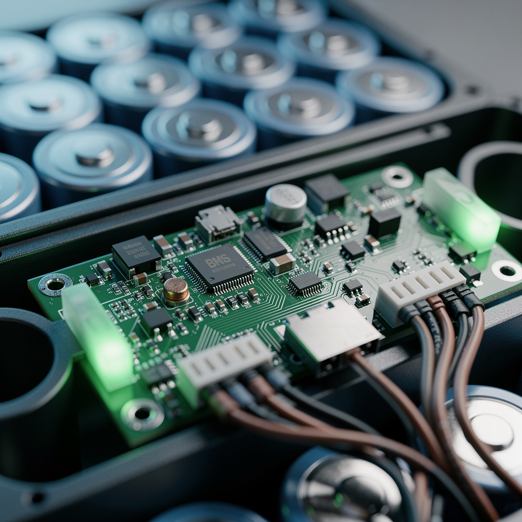
What is a Battery Management System?
A Battery Management System (BMS) is the brain of your lithium battery bank. This essential electronic system monitors, protects, and optimizes your battery’s performance, ensuring safe operation while maximizing lifespan. Without a proper BMS, lithium batteries are vulnerable to dangerous conditions including overcharging, deep discharge, and thermal runaway.
While many battery users focus on cell selection and capacity, the BMS is arguably the most critical component in your system. A high-quality BMS prevents catastrophic failures, balances cell voltages for optimal performance, and provides valuable monitoring data. Understanding how BMS units work empowers you to select the right system for your application and troubleshoot issues effectively.
Why You Need a BMS
Protection Functions
Lithium batteries require precise voltage and current management. A BMS provides multiple layers of protection:
Overcharge Protection: Prevents charging beyond safe cell voltages. For LiFePO4 batteries, this means cutting off charging when any cell reaches 3.65-3.70V. Overcharging causes lithium plating on the anode, creating internal shorts and fire hazards.
Over-Discharge Protection: Stops discharge before cells reach damaging low voltages. LiFePO4 cells should not discharge below 2.50V. Deep discharge causes copper dissolution from the current collector, permanently damaging cells.
Overcurrent Protection: Monitors charge and discharge currents, disconnecting the battery if safe limits are exceeded. Prevents damage from short circuits or excessive loads.
Temperature Protection: Disables charging or discharging when temperatures exceed safe ranges. Critical for preventing thermal runaway and avoiding lithium plating during cold-weather charging. For how to read and set the specific low-temperature charge cutoff values on JK and Daly boards, the BMS charge temperature cutoff guide walks through the configuration menus and the threshold values that protect cells without blocking too much winter charging time.
Cell Balancing
Individual cells in a series string charge and discharge at slightly different rates due to manufacturing variations and aging. Over time, these differences compound, creating significant voltage imbalances.
A BMS with active balancing monitors each cell’s voltage and transfers energy from higher-voltage cells to lower-voltage cells. This balancing ensures all cells reach full charge simultaneously and prevents individual cells from being overcharged or over-discharged while the pack as a whole appears healthy.
Without balancing, strong cells mask weak cells during charging. The charger sees the overall pack voltage and stops, leaving some cells undercharged while others are overcharged. The weak cells then discharge faster, reaching dangerous low voltages while the pack appears to have remaining capacity.
State of Charge Estimation
Modern BMS units calculate battery state of charge (SOC) using sophisticated algorithms. Unlike lead-acid batteries where voltage directly correlates with SOC, lithium batteries maintain relatively flat voltage curves throughout most of their discharge.
BMS algorithms track current flowing in and out of the battery (coulomb counting) combined with voltage measurements and temperature compensation. This provides accurate SOC readings typically within 2-5% of actual charge level.
BMS Architecture and Components
Hardware Components
A BMS consists of several functional blocks:
Cell Monitoring Unit (CMU): Measures voltage of each series cell using high-precision analog-to-digital converters. Quality BMS units achieve 1-5mV measurement accuracy.
Temperature Sensors: Monitor battery temperature at multiple points. Typically use NTC thermistors (negative temperature coefficient resistors) that change resistance predictably with temperature.
Current Sensing: Measures charge and discharge current using shunt resistors or Hall effect sensors. High-precision current measurement enables accurate SOC calculation and overcurrent detection.
Balancing Circuits: Transfer energy between cells to maintain voltage equality. Active balancing uses DC-DC converters or capacitive/inductive transfer. Passive balancing dissipates excess energy as heat through resistors.
Protection Switches: Control charge and discharge paths using MOSFETs or contactors. High-current BMS units use multiple parallel MOSFETs to handle large loads while minimizing voltage drop and heating.
Microcontroller: The BMS brain processes sensor data, executes protection algorithms, controls balancing, and manages communications.
Balance Wire Configuration
Balance wires connect the BMS to each cell junction in the series string. For a 16S (16 cells in series) battery, the BMS has 17 balance wires:
- Wire 1: Most negative cell terminal (B-)
- Wires 2-16: Junction between cells
- Wire 17: Most positive cell terminal (B+)
Proper balance wire installation is critical. Reversed connections damage the BMS and create fire hazards. Double-check every connection before applying power.
Main Power Connections
BMS units connect in series with the battery negative leg:
- Battery negative (B-) connects to BMS B- terminal
- BMS P- terminal provides protected negative output to loads and chargers
- Battery positive (B+) connects directly to system positive through appropriate fusing
This configuration allows the BMS to disconnect both charging and discharging by opening internal switches. When protection triggers, the BMS isolates the battery from both loads and charging sources.
Types of BMS Systems
Distributed vs. Centralized BMS
Centralized BMS: All monitoring, balancing, and protection circuits reside on a single circuit board mounted on the battery. Most common for DIY and small-to-medium battery systems. Simpler installation but limited scalability.
Distributed BMS: Cell monitoring units mounted on individual cells or modules communicate with a central controller via data bus (typically CAN bus). Used in electric vehicles and large commercial systems. More complex but scalable to thousands of cells.
For residential and DIY applications, centralized BMS units offer the best balance of features, simplicity, and cost.
Active vs. Passive Balancing
Passive Balancing: Bleeds excess energy from high-voltage cells as heat through resistors. Simple, inexpensive, but wastes energy and generates heat. Typically limits balancing current to 50-200mA.
Passive balancing is adequate for most stationary applications where charging opportunities are plentiful. The energy “wasted” in balancing is typically minimal compared to total system capacity.
Active Balancing: Transfers energy from high cells to low cells using capacitors, inductors, or DC-DC converters. More efficient (80-95% energy transfer) and faster balancing (up to 1-2A). More complex and expensive.
Active balancing is beneficial for:
- Systems with limited charging opportunities (mobile applications)
- Large capacity batteries where passive balancing would take excessive time
- Applications where energy efficiency is paramount
For most DIY battery builders, passive balancing provides adequate performance at lower cost.
Smart BMS vs. Basic Protection Boards
Basic Protection Boards: Simple circuits providing only overcharge and over-discharge protection. Low cost ($10-30) but limited functionality. Typically used in small battery packs (power tools, e-bikes) where monitoring is not required.
Smart BMS: Microcontroller-based systems with comprehensive protection, monitoring, and communication capabilities. Cost $50-300 depending on current rating and features. Essential for DIY energy storage systems.
Smart BMS features include:
- Individual cell voltage monitoring
- Temperature monitoring and protection
- Current measurement and SOC calculation
- Active or passive cell balancing
- Bluetooth or WiFi connectivity
- Configuration via smartphone apps or PC software
- Data logging and historical statistics
- Programmable protection thresholds
- Remote monitoring capabilities
Selecting the Right BMS
Voltage Rating
Select a BMS rated for your battery voltage:
- 4S BMS for 12V systems (4 cells × 3.2V = 12.8V nominal)
- 8S BMS for 24V systems (8 cells × 3.2V = 25.6V nominal)
- 16S BMS for 48V systems (16 cells × 3.2V = 51.2V nominal)
Some BMS units support multiple series configurations through software selection. Others are hardware-specific. Verify compatibility with your planned cell configuration.
Current Rating
BMS current rating must exceed your maximum expected load with safety margin:
- Determine maximum continuous current from your loads
- Add 25-50% margin for future expansion and safety
- Consider surge currents (motor starting, etc.)
- Select BMS with continuous and peak current ratings exceeding requirements
Common residential BMS ratings:
- Small systems (RVs, cabins): 60-100A
- Medium residential: 100-150A
- Large residential/off-grid: 200-300A
Higher current ratings require more parallel MOSFETs and larger heat sinks, increasing cost. Size appropriately for your actual needs.
Quality and Reliability
Not all BMS units are equal. Consider these factors:
Build Quality:
- Thick copper traces for high current paths
- Adequate heat sinking for MOSFETs
- Quality connectors and terminals
- Conformal coating for moisture protection
Component Quality:
- Name-brand MOSFETs (Infineon, Vishay, IR)
- High-precision voltage reference chips
- Reliable microcontroller with adequate memory
- Quality connectors rated for vibration and corrosion resistance
Manufacturer Reputation:
Established BMS manufacturers include:
- JK BMS (formerly JiKong): Feature-rich, good app support, affordable
- Daly: Budget option with basic functionality
- JBD (Jiabaida): Reliable with active balancing options
- Overkill Solar: Popular for DIY builds, good community support
- REC Active BMS: High-end with active balancing
- Orion BMS: Professional-grade with extensive features
Avoid no-name BMS units from unknown manufacturers. Poor-quality BMS units may have inaccurate voltage measurement, inadequate protection response times, or premature component failure.
BMS Configuration and Programming
Protection Thresholds
Program appropriate protection parameters for your specific cells:
LiFePO4 Cell Settings (typical):
- Overcharge voltage: 3.60-3.65V (some allow 3.70V)
- Overcharge recovery: 3.40-3.50V (hysteresis prevents oscillation)
- Over-discharge voltage: 2.50-2.80V (conservative: 2.80V)
- Over-discharge recovery: 3.00-3.20V
- Charge overcurrent: 0.5-1.0C (0.5C = half capacity rating)
- Discharge overcurrent: 1.0-2.0C
- Short circuit protection: Immediate shutdown
Temperature Settings:
- Charge disable below: 0°C (32°F)
- Charge disable above: 45-50°C (113-122°F)
- Discharge disable above: 60°C (140°F)
- Resume normal operation: Return to safe temperature range
Consult your cell manufacturer’s datasheet for specific recommendations. Conservative settings extend battery life but may limit usable capacity slightly.
Balancing Configuration
Configure cell balancing parameters:
- Balance start voltage: Cells begin balancing when they reach this voltage (typically 3.40-3.45V for LiFePO4)
- Balance delta: Maximum voltage difference allowed between cells before aggressive balancing begins (typically 10-50mV)
- Balance current: Rate of energy transfer during balancing (50mA-2A depending on BMS type)
Balancing typically occurs only during charging, particularly at the end of the charge cycle when cells reach high voltages. Some advanced BMS units balance continuously or during discharge as well.
Communication and Monitoring Setup
Modern BMS units offer multiple connectivity options:
Bluetooth Connectivity:
- Smartphone apps (iOS/Android) for real-time monitoring
- View individual cell voltages, temperatures, current
- Adjust configuration settings
- View historical data and charts
- Receive alarm notifications
WiFi/Ethernet:
- Remote monitoring via internet
- Integration with home automation systems
- Data logging to cloud services
Serial Communications (RS485/CAN):
- Integration with charge controllers and inverters
- Victron VE.Bus, CAN bus protocols
- Professional monitoring systems
Display Screens:
- Local LCD displays showing key parameters
- Some BMS units include integrated screens
- External display modules available
BMS Installation Best Practices
Physical Installation
Mount the BMS securely within your battery enclosure:
- Position for adequate ventilation and cooling
- Avoid mounting directly on hot components
- Ensure access for troubleshooting and configuration
- Protect from moisture and dust
- Use vibration-resistant mounting for mobile applications
Wiring Considerations
Proper wiring ensures accurate measurements and reliable protection:
- Use appropriate gauge wire for current rating
- Keep balance wires as short as practical (reduces noise)
- Route balance wires away from high-current conductors
- Use consistent wire colors and label everything
- Apply strain relief to prevent connection failures
Balance wire gauge is not critical since balancing current is low. 18-22 AWG wire is adequate for most applications.
Current Sensing
For accurate SOC calculation and overcurrent protection:
- Position current shunt in negative return path
- Ensure all current flows through the shunt (no parallel paths)
- Calibrate current zero point with no load connected
- Verify current reading accuracy with known loads
Integration with Charging Systems
Your BMS should coordinate with charge controllers and inverters:
- Some BMS units provide control outputs to signal chargers
- Victron systems integrate via VE.Bus or CAN
- Program charge controllers to respect BMS protection
- Install battery isolation contactors if required by local codes
Proper integration with solar and charging systems ensures safe, coordinated operation.
Troubleshooting BMS Issues
Common Problems and Solutions
Inaccurate Voltage Readings:
- Check balance wire connections for looseness or corrosion
- Verify no wires are reversed
- Calibrate BMS if calibration function available
- Check for interference from nearby high-current cables
Premature Low Voltage Cutoff:
- Check individual cell voltages (one weak cell triggers cutoff)
- Verify cutoff voltage settings are appropriate
- Inspect for cell imbalance requiring balancing
- Confirm load is not exceeding battery capability
Overheating:
- Verify current is within BMS rating
- Improve ventilation around BMS
- Check for loose connections creating resistance
- Add supplemental cooling if necessary
Bluetooth Connectivity Issues:
- Ensure BMS has power (may require charging to activate)
- Move closer to BMS (Bluetooth range is limited)
- Restart smartphone app
- Check for app updates
- Verify correct BMS model selected in app
Excessive Cell Imbalance:
- Verify balancing is enabled in BMS settings
- Check balance start voltage is appropriate
- Ensure cells are adequately matched during construction
- Perform manual balance charge if needed
- Inspect for damaged cells requiring replacement
BMS Failure Modes
Recognize when BMS replacement is needed:
- Persistent inaccurate readings after calibration
- Failure to trigger protection when limits exceeded
- MOSFETs failed (high voltage drop, excessive heating)
- Physical damage to circuit board
- Corrosion from moisture exposure
- Outdated firmware without manufacturer support
A failed BMS requires immediate replacement. Never operate lithium batteries without functional protection.
Advanced BMS Features
SOC and SOH Algorithms
Beyond basic voltage monitoring, sophisticated BMS units track:
State of Charge (SOC): Percentage of remaining capacity calculated through current integration, voltage curves, and machine learning algorithms.
State of Health (SOH): Indicator of battery degradation. Compares current capacity and internal resistance to original specifications. Helps predict end of battery life.
State of Power (SOP): Real-time calculation of maximum charge and discharge power available based on current battery condition and temperature.
Predictive Analytics
Advanced systems predict future performance:
- Remaining cycle life estimation
- Capacity fade prediction
- Optimal charging profile suggestions
- Maintenance scheduling recommendations
Integration with Smart Home Systems
Modern BMS units connect to broader ecosystems:
- Home Assistant integration for automation
- Solar production coordination
- Load management and prioritization
- Grid interaction optimization (time-of-use rates)
- Voice assistant compatibility (Alexa, Google Home)
BMS Selection Guide by Application
Small Mobile Systems (RVs, Boats)
- 60-100A rated BMS
- Bluetooth monitoring essential
- Passive balancing adequate
- Vibration-resistant design
- Compact size for tight spaces
Recommended: JK BMS 100A, Daly 100A Smart BMS
Residential Solar Storage
- 100-200A rated BMS
- Active balancing beneficial for daily cycling
- WiFi or Ethernet for remote monitoring
- Integration with solar charge controllers
- Long-term reliability focus
Recommended: JK BMS 150-200A, REC Active BMS, Batrium
Off-Grid Systems
- 150-300A rated BMS
- High reliability and accuracy
- Generator control integration
- Comprehensive monitoring and logging
- Field serviceability
Recommended: JK BMS 200A+, REC BMS, Orion BMS
Conclusion
The Battery Management System is the unsung hero of your energy storage installation. While batteries store the energy and inverters convert it, the BMS ensures everything operates safely, efficiently, and reliably. Understanding BMS functionality empowers you to select the right system, install it properly, and maintain it for years of trouble-free service.
Key takeaways for BMS selection and use:
- Never operate lithium batteries without a quality BMS
- Size your BMS for your actual current needs plus margin
- Invest in a smart BMS with monitoring and balancing capabilities
- Program protection settings appropriate for your specific cells
- Verify proper installation of balance wires and current sensing
- Integrate BMS with your charging and monitoring systems
- Perform regular checks of cell balance and BMS operation
As you build your battery bank, give the BMS the attention it deserves. Choose quality over cheapest price, follow manufacturer guidelines, and double-check every connection. The BMS is your primary safety device, protecting your investment and your property.
Modern BMS technology continues evolving, offering better monitoring, more sophisticated algorithms, and tighter integration with renewable energy systems. By understanding these systems today, you position yourself to take advantage of future innovations while maintaining safe, reliable battery storage.
Your battery bank represents a significant investment in energy independence. The BMS protects that investment while optimizing performance. Treat it as the critical component it is, and your battery system will reward you with years of dependable service.