Important Disclaimer
BatteryStorageHQ provides educational content and estimates only. We are not certified installers, financial advisors, or electricians. Always consult with licensed professionals.
A safe home battery system comes down to four non-negotiables: every conductor sized to carry more current than its overcurrent device will ever let pass, a DC-rated fuse or breaker at every energy source, every metal enclosure bonded to ground, and a battery chemistry — LiFePO4 — that fails far less violently than the NMC cells in your laptop. Get those right and the rest is detail.
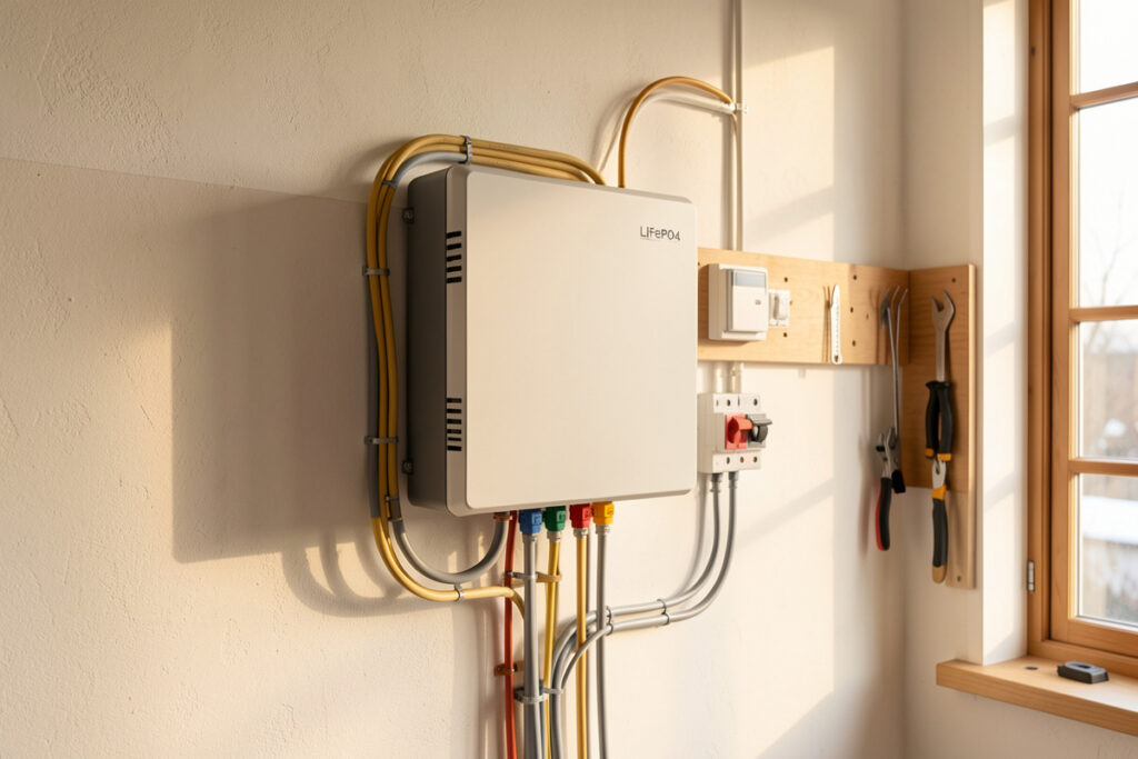
I build LiFePO4 banks from bare prismatic cells here in Sweden — 16S, ~280 Ah grade-A EVE cells wired to 51.2 V nominal, compression-fixtured, top-balanced on a bench supply, running a hybrid inverter that backs the welder, the CNC and the sauna pre-heat. The bank itself is the easy part. The wiring, fusing, grounding and code compliance around it is where I see DIY builders cut the corners that start fires. This guide is the load-bearing wall of everything else on the site: it ties together wire sizing, fusing, busbars, grounding, code, ventilation and thermal-runaway prevention into one mental model so you can size a safe system instead of copying someone’s parts list off a forum.
The four-layer safety model: how a battery system actually protects you
A battery system is safe when four independent layers each do their job: conductor ampacity, overcurrent protection, equipment grounding, and chemistry/enclosure containment. No single layer is allowed to be the only thing standing between you and a fault. A 51.2 V LiFePO4 bank can dump 5,000–15,000 A into a dead short — that is the number that should scare you, and the number every design decision answers to.
Think of it as defense in depth. The conductor is sized so it never overheats under normal load. The overcurrent device opens before the conductor reaches that limit under fault. The grounding system gives fault current a low-impedance path back to source so the device trips fast and so no exposed metal ever sits at a dangerous potential. And the chemistry plus the enclosure mean that if everything else fails, what you get is a vented cell and an alarm, not a roof fire. When I commission a bank, I test each layer separately — clamp-meter the loaded conductors, verify the fuse interrupt rating against the bank’s short-circuit current, ohm out every bond, and confirm the BMS cutoffs before the inverter ever sees the pack.
Wire and cable: ampacity is the foundation everything else sits on
Conductor sizing is the first decision and the one people get wrong most often. The rule is simple to state: the wire must be able to carry more current, continuously, than the fuse or breaker protecting it will ever allow. For continuous loads — and a home battery feeding an inverter is a continuous load — you size to 125% of the expected current, then choose an overcurrent device the conductor can survive. A 51.2 V bank feeding a 6,000 W inverter pulls roughly 117 A continuous at the low-voltage end; that wants 2/0 AWG copper at 75 °C in most installs, not the 4 AWG someone tells you “is fine.”
Ampacity is not a single number. It drops with conductor temperature rating, with ambient heat, with how many conductors share a conduit, and with cable length once voltage drop enters the picture. On a battery bank the high-current battery-to-inverter cables and the battery interconnects are the conductors that matter most, because that is where fault current concentrates. I work through the full method — temperature columns, derating, and a 1–2% voltage-drop target for the main DC run — in the dedicated wire and cable ampacity sizing guide. Undersized DC cable is the single most common dangerous mistake I see in photos people send me.
Fusing and breakers: the device that decides whether a fault becomes a fire
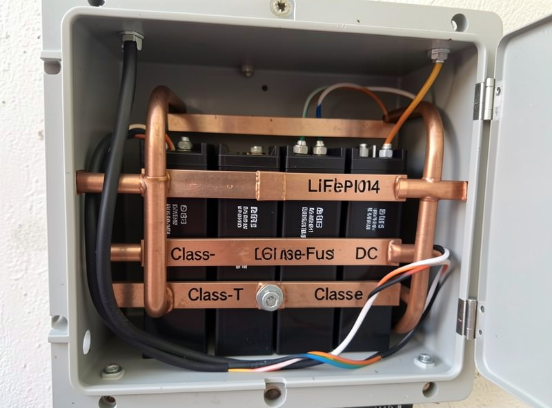
Every source of energy gets an overcurrent device, sized to protect the smallest conductor it feeds, rated for DC, and — critically on lithium — rated to interrupt the bank’s available short-circuit current. This is where a Class-T fuse earns its place. A class-T fuse carries a 20,000 A interrupt rating; a cheap automotive ANL or a DC breaker rated for 5,000 A will weld itself shut or arc when a 51.2 V LFP bank faults, and an overcurrent device that cannot open is worse than none. I run a Class-T as the main battery fuse on every bank I build, mounted as close to the positive terminal as practical.
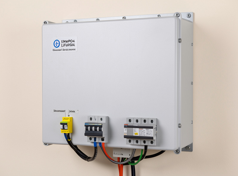
Breakers and fuses are not interchangeable by amp rating alone. A breaker gives you a switchable disconnect; a fuse gives you a higher interrupt rating in a smaller package. Most of my builds use both — a Class-T main fuse for fault protection and a DC breaker as the service disconnect. The voltage rating must meet or exceed system voltage on a DC basis (a breaker marked 65 VDC is fine for a 51.2 V bank; one marked only for AC is not). The full selection logic — interrupt ratings, fuse classes, breaker types, where each device goes — is in the fusing and breakers guide.
Busbars and lugs: the connections that quietly cause most heat faults
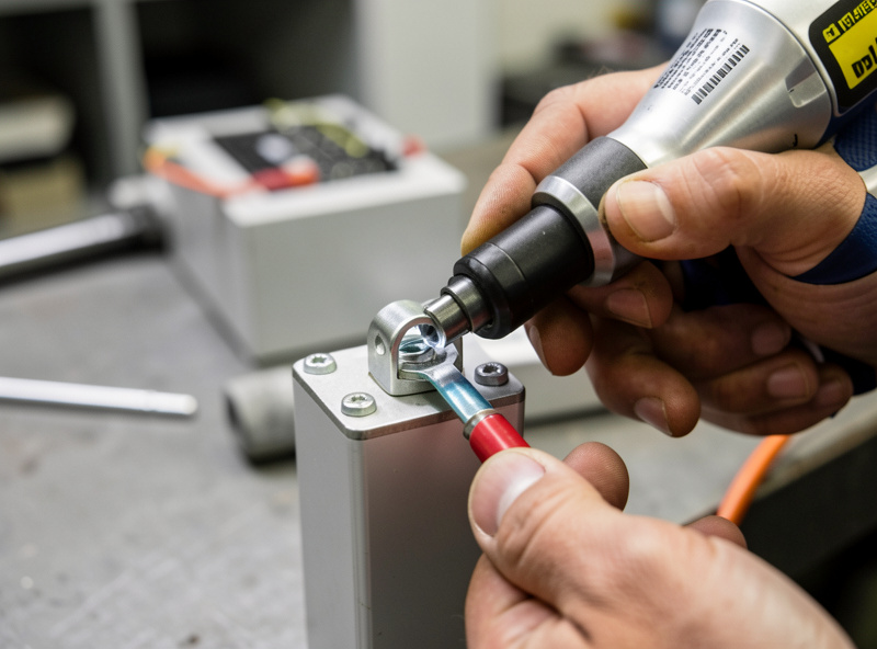
A loose or under-torqued lug is the most common cause of a hot connection, and a hot connection is how a perfectly-sized cable still starts a fire. Every high-current joint needs the right lug, crimped (not soldered) for a 280 Ah-class bank, torqued to the terminal manufacturer’s spec, and protected with an anti-oxidant where dissimilar metals meet. A busbar rated below the fault current it carries is a hidden weak point most parts lists never check.
Busbar sizing follows the same ampacity logic as cable — cross-sectional area sets the current it can carry without overheating. I torque every M8 terminal on my bank to spec with a calibrated driver, mark each with a paint pen so I can see at a glance if one has backed off, and re-check torque after the first few thermal cycles because copper relaxes. The full treatment — lug selection, crimp vs. solder, torque tables, busbar sizing — lives in the busbars and lugs guide.
Grounding and bonding: the layer that keeps metal safe to touch
Grounding and bonding are two different jobs people constantly conflate. Bonding ties all the metal enclosures, racks and frames together and to a common equipment-grounding conductor so no exposed surface can ever sit at a dangerous voltage. Grounding (the system-bonding jumper) connects one current-carrying conductor — typically the DC negative — to that ground at exactly one point, so a ground fault has a defined return path and the overcurrent device trips. Two bonding points create a ground loop; zero leaves metal floating and fault current with nowhere to go.
On my system the inverter is the single point where the DC negative is bonded to ground, per the inverter manufacturer’s manual and NEC practice, and every enclosure — battery box, inverter chassis, charge-controller case — lands on the equipment-grounding conductor. I ohm out every bond at commissioning; anything above a fraction of an ohm gets re-done. Get this wrong and a single insulation failure can energize a cabinet you lean on. The complete method is in the grounding and bonding guide.
NEC and code: what the inspector actually checks
In the US, a home energy storage system lives mostly under NEC Article 706 (Energy Storage Systems), with Article 480 (storage batteries), 690 (solar PV) and 705 (interconnection) all touching it, and NFPA 855 plus the local fire code governing siting and quantity. Equipment must be listed — UL 9540 for the system, UL 1973 for the battery — disconnects and labeling are required, and there are real limits on how much energy you can put in a given location and how far units must sit apart.
Code is not bureaucratic theater here; almost every clause maps to a failure I have seen or read incident reports on. The disconnect requirement means a firefighter can de-energize your system. The listing requirement means the cells passed abuse testing. The separation and quantity limits in NFPA 855 exist because of thermal-runaway propagation. I treat code as the floor, not the ceiling — but if you are doing a permitted install, the inspector’s checklist is non-negotiable. I break down which articles apply to a residential build, and where DIY packs get complicated, in the NEC code for home energy storage guide.
Enclosure ventilation: heat out, gases out, the right way per chemistry
Ventilation requirements depend entirely on chemistry, and this is where lead-acid habits get dangerously misapplied to lithium. Flooded lead-acid off-gasses hydrogen continuously on charge and must be vented to stay below the 4% hydrogen lower-explosive-limit. Sealed LiFePO4 does not off-gas hydrogen in normal operation — it needs ventilation for heat dissipation and a path for the flammable, toxic gases a cell vents only during a thermal event. Sealing an LFP bank in an airtight box is the wrong instinct in both directions.
My bank lives in a ventilated enclosure that lets convective heat escape and would let vent gas disperse rather than accumulate, with temperature sensing feeding the same Home Assistant dashboard that watches per-cell voltage and SoC. The numbers — clearances, airflow, why a garage install has different rules than a living space, and the lead-acid vs. lithium distinction — are in the enclosure ventilation guide.
Thermal runaway: why LFP is the safe chemistry, and how to keep it that way
Thermal runaway is the failure everyone fears, and the honest news is that LiFePO4 is dramatically more resistant to it than the NMC chemistry in EVs and laptops. LFP’s thermal-runaway onset is well above 250 °C versus roughly 150–210 °C for NMC, and LFP does not release oxygen as it decomposes, so it cannot self-sustain a fire the same way. That is the single biggest reason I build home banks from LFP and would not put NMC on a wall in my workshop.
“More resistant” is not “immune.” Prevention is mechanical protection against crush and puncture, never charging below 0 °C (lithium plating is the slow killer that turns into an internal short), a BMS that actually cuts off on over-voltage, over-temperature and over-current, and the fusing and bonding above so an external fault never gets the chance to heat a cell. I cover the whole prevention stack — what triggers runaway, what LFP does differently, and the layered defenses — in the thermal runaway prevention guide, which deepens the broader battery storage safety overview.
How the layers compare: where each one fails and what catches it
The table below is the mental model I use when I audit a build. Each safety layer addresses a specific failure mode, and the point of defense-in-depth is that the next layer catches what the previous one misses.
| Safety layer | Failure it prevents | What it must be rated for | Most common mistake |
|---|---|---|---|
| Conductor ampacity | Cable overheating under load | 125% of continuous current, at install temperature | Sizing to load, not to the breaker; ignoring heat derating |
| Overcurrent device | Fault current becoming a fire | Protect smallest conductor; DC-rated; interrupt ≥ bank short-circuit current | ANL/automotive fuse with too-low interrupt rating on LFP |
| Busbar / lug joint | Hot connection at the terminal | Cross-section ≥ cable ampacity; torqued to spec | Under-torqued or solder-only lugs that relax and heat |
| Equipment bonding | Live metal you can touch | Low-impedance EGC to every enclosure | Floating enclosures or two system-bond points |
| BMS cutoffs | Overcharge / cold-charge / over-current | Cell-level V, T and current limits | Cheap BMS with no low-temp charge cutoff |
| Chemistry + enclosure | A single-cell fault becoming a catastrophe | LFP cells, vented non-airtight enclosure | Sealed box; or NMC cells on a living-space wall |
Where the BMS fits — and where it does not
People treat the BMS as the whole safety system. It is not. A BMS protects the cells from electrical and thermal abuse — over-voltage, under-voltage, over-current, and on a good board, low-temperature charge lockout. It does nothing about an external short between the battery and the fuse, nothing about a loose busbar, nothing about an ungrounded enclosure, and nothing about ventilation. It is one layer among six. The cheapest BMS is rarely the cheapest total cost precisely because the corners it cuts — no temperature sensing, marginal balancing, a low-current MOSFET path that nuisance-trips when the welder fires — are the corners that matter. I run a JK active-balancer BMS as the daily driver on the main bank and treat active-vs-passive balancing as a settled, tested opinion, which I get into in the BMS guide and the below-freezing charge cutoff article.
Putting it together: the order I commission a system in
The sequence matters. I top-balance and compression-fixture the cells first (covered in the top-balancing guide and the full DIY bank build guide), then size and run conductors, then install busbars and torque every joint, then the main Class-T fuse and disconnect, then bond every enclosure and set the single system-ground point, then configure the BMS cutoffs, then finally bring up the inverter and set an LFP-correct charge profile — absorption around 55.2–56 V and float low or off. Only then does the bank see real load. Each step is verified before the next. That discipline — not any single component — is what makes a home battery system safe enough to mount on a wall near where my family sleeps.
Frequently Asked Questions
Is a LiFePO4 home battery safe to install indoors?
Yes, when wired correctly. LiFePO4 resists thermal runaway far better than NMC, with onset above 250 C and no oxygen release. It still needs proper DC fusing, bonded enclosures, a working BMS and ventilation. Follow NEC 706 and NFPA 855 siting and quantity rules for indoor installs.
What size fuse does a 51.2V LiFePO4 battery need?
Size the fuse to protect the smallest conductor it feeds, rated for DC, with an interrupt rating above the bank’s short-circuit current. A Class-T fuse with a 20,000 A interrupt rating is the standard main fuse for a 51.2 V LFP bank because cheaper ANL fuses can fail to open on a lithium fault.
Do I need to ground a DIY battery bank?
Yes. Bond every metal enclosure to a common equipment-grounding conductor, and connect the DC negative to ground at exactly one point per your inverter manual. This keeps exposed metal safe to touch and gives fault current a defined path so the overcurrent device trips quickly.
Does a LiFePO4 battery need ventilation?
It needs ventilation for heat dissipation and to disperse vent gas during a fault, but not the continuous hydrogen venting flooded lead-acid requires. Never seal an LFP bank in an airtight box. Lead-acid off-gasses hydrogen on every charge; sealed lithium does not in normal operation.
What is the most common dangerous wiring mistake?
Undersized DC cable between the battery and inverter, paired with an overcurrent device that cannot interrupt the bank’s fault current. Size conductors to 125% of continuous current and verify the fuse interrupt rating against the bank’s available short-circuit current, which can exceed 5,000 A.
Which NEC articles apply to home battery storage?
Article 706 governs energy storage systems, with Article 480 (batteries), 690 (solar PV) and 705 (interconnection) often applying too. NFPA 855 and the local fire code govern siting, separation and quantity. Equipment should be listed to UL 9540 (system) and UL 1973 (battery).
Labeling, disconnects and the documentation that saves a firefighter’s life
The layer most DIY builders skip entirely is documentation, and it is the one a first responder relies on. Every disconnect needs a durable label stating what it isolates and its ratings; the system needs a placard identifying it as an energy storage system with its nominal voltage and chemistry; and a clearly marked main disconnect must let someone de-energize the bank without opening the enclosure. I keep a laminated one-page diagram on the inside of the battery-room door — string layout, fuse ratings, the single ground-bond point, BMS cutoff settings and the inverter’s charge profile. It cost me twenty minutes and it is the difference between a controlled response and a firefighter refusing to enter.
This documentation is also how the safety layers stay safe over years. A bank is not commissioned once and forgotten — torque relaxes, balancers drift, a connection corrodes. My Home Assistant dashboard logs per-cell voltage, pack temperature, daily PV and load so I can see drift before it becomes a fault, and the laminated sheet tells future-me what the system was supposed to be. Treat the paperwork as the seventh safety layer; it is the one that makes the other six maintainable. The maintenance and monitoring guide covers the ongoing checks, and the sizing guide covers the loads those safety margins are built around.
Related Guides
- Wire and Cable Ampacity Sizing for Battery Systems
- Fusing and Breakers for Battery Systems
- Busbars and Lugs for Connections
- Grounding and Bonding Battery Systems
- NEC Electrical Code for Energy Storage
- Enclosure Ventilation for Batteries
- Thermal Runaway Prevention Guide
- DIY LiFePO4 Battery Bank Build Guide
- Battery Storage Safety Overview