Important Disclaimer
BatteryStorageHQ provides educational content and estimates only. We are not certified installers, financial advisors, or electricians. Always consult with licensed professionals.
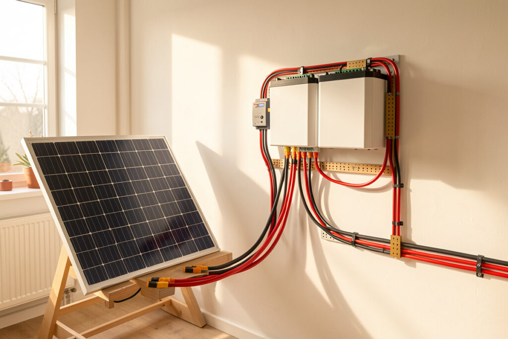
The connectors and cable between your panels and your bank are where most home solar systems quietly lose energy and, occasionally, catch fire. A single corroded MC4 or an under-crimped lug can drop 0.3–0.5 V under load — on a 48 V bank pulling 60 A that is roughly 18–30 W burned as heat at one joint, every hour the sun shines. This guide covers the whole connector and DC wiring layer: the hardware between the array and the battery terminals, and how to make every junction in it electrically tight and mechanically honest.
I build LiFePO4 banks from bare prismatic cells here in Sweden — a 16S, 280 Ah EVE LF280K bank at 51.2 V nominal, fed by a modest south-facing array through a Victron SmartSolar MPPT, with a MultiPlus-II carrying the workshop loads. After enough winters watching per-cell voltage and daily PV scroll past in Home Assistant, I have learned that the cells and the inverter get all the attention while the connectors quietly decide whether the system is reliable. This is the layer the unboxing videos skip, because nobody sells a sealed appliance that hides it.
The DC Connector Layer: What Sits Between Panels and Bank
Your DC system has three distinct wiring zones, and each one wants different hardware. The PV side — panel to combiner to charge controller — runs at high voltage and modest current, and lives on MC4 connectors and PV wire. The battery side — controller and inverter to the bank — runs at low voltage and brutal current, and lives on crimped lugs, busbars, and Class-T fuses. Between them sit the enclosure penetrations, the strain relief, and the small DC disconnects. Treat these as one continuous chain, because the system is only as good as its worst junction.
The mistake I see most often is buying a beautiful inverter and a grade-A cell stack, then terminating everything with a $9 hardware-store crimper and bare copper lugs. The bank I built is fixtured, torqued, and fused to spec, but its real-world internal resistance is set as much by eight crimped lugs and four connector pairs as by the cells themselves. Every joint you add is a small resistor in series with your whole system. The job of good connector hardware is to keep each of those resistances down in the fraction-of-a-milliohm range where it belongs, and to keep it there for ten years of thermal cycling.
If you want the gauge math behind these cables — how many amps a given conductor carries before it overheats — that lives in my battery wire sizing and ampacity guide, and the battery-terminal side is covered in the busbar and lug selection guide. This article is deliberately about the field connectors and the crimps themselves: the parts that fail in service, not the parts you size on a calculator once and forget.
PV-Side Connectors: MC4 and the Counterfeit Problem
On the panel side, the MC4 is the de-facto standard, and it is genuinely good hardware when it is genuine. A properly crimped and seated MC4 pair has a contact resistance in the low single-digit milliohms and an IP67 seal that survives years on a roof. The catch is that the market is flooded with look-alikes, and a counterfeit MC4 mated to a real one makes a connection that looks perfect and runs hot — the contact geometry and copper alloy simply do not match.
I keep a cheap PWM controller and a bag of mystery connectors on the bench purely as a teaching reference for what goes wrong. The lesson is consistent: never mate two different brands of MC4, always crimp with the die that matches the contact, and treat any connector that runs warmer than its cable as a defect to be replaced, not monitored. The full crimping, sealing, and counterfeit-spotting workflow is in MC4 connectors explained — it is the single most useful thing to get right on the PV side.
One number worth internalizing: a high-resistance connector does not announce itself at low current. At 5 A on a cloudy morning a bad MC4 might drop 50 mV and feel cool. At 12 A in full sun the same junction dissipates four times the power and becomes a hot spot. This is why a connection that “worked fine all winter” can fail in June, and why I measure voltage drop under real load rather than trusting a cold continuity check.
Battery-Side Connectors: Lugs, Anderson, and PowerPole
The battery side is a different world. Voltages are low — 12, 24, or 48 V — but currents are enormous. My inverter can pull well over 150 A from the 48 V bank when the workshop surge hits, and a 12 V system doing the same power would see four times that. Here the hardware is crimped copper lugs onto busbars and terminals, with Anderson SB connectors and PowerPoles handling the disconnectable, portable, and modular junctions.
Anderson SB50, SB120, and SB175 housings are the honest workhorses for anything you need to unplug under load — battery-to-cart, portable packs, removable banks. PowerPole 15/45 connectors handle the lower-current accessory and parallel-distribution side. The two families solve different current ranges, and people constantly reach for the wrong one. Where each belongs — with the current ratings and the genderless-housing logic that makes Andersons so practical — is laid out in the Anderson SB and PowerPole guide.
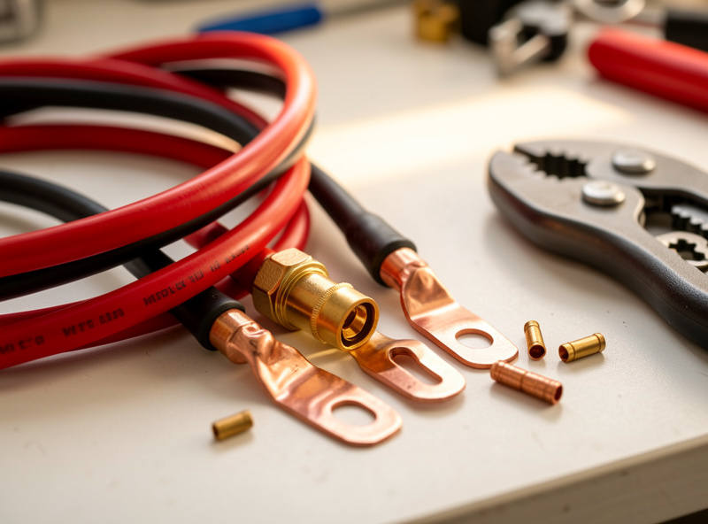
For the fixed, high-current terminations — cell-to-busbar, busbar-to-fuse, fuse-to-inverter — there is no connector at all, just a crimped lug bolted down and torqued. That crimp is the most safety-critical joint in the whole system, because a cold or partial crimp here carries the full battery current and can glow red. Doing it without a cold joint, with the right tool and the right inspection, is its own discipline: see how to crimp battery and solar lugs. If you skip one section of this hub, do not let it be that one.
Choosing the Cable Itself: PV Wire vs Welding Cable
The conductor between connectors matters as much as the terminations. On the PV side you want true PV wire (or USE-2) — double-insulated, UV-stable, rated for the cold Voc rise a string sees on a clear winter morning. On the battery side, the debate is PV wire and battery cable versus flexible welding cable, and it is not as simple as “welding cable is more flexible so use it everywhere.”
Welding cable is gorgeously flexible because it uses many fine strands, which is exactly what you want snaking around a tight enclosure. But it is rarely rated for outdoor UV or for the temperature and voltage class a code inspector wants to see, and the fine strands demand tinning or a proper lug to terminate cleanly. PV wire and proper battery cable trade some flexibility for ratings and durability. I run both in different places for honest reasons, and the trade-offs — ampacity, insulation rating, UV, terminability — are worked through in PV wire vs welding cable for DC runs.
Cold matters here too. On a clear January morning my string’s open-circuit voltage climbs well above its nameplate 25 °C figure — crystalline silicon’s Voc rises roughly 0.3% per degree below 25 °C, so a −15 °C panel can sit 12% over its rated Voc. That is a wiring-margin and insulation-rating issue, not trivia; I cover the controller-side consequences in the cold-weather string Voc guide.
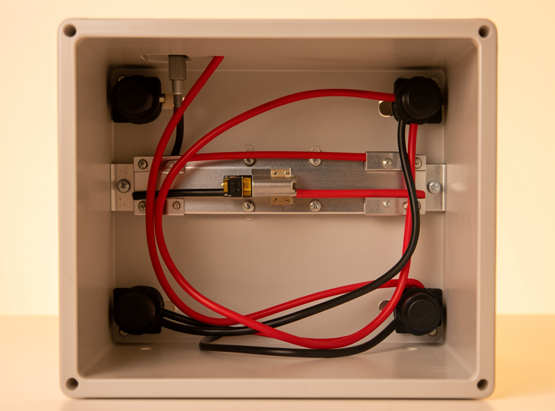
Enclosure Penetrations: Cable Glands and Strain Relief
Every cable that enters a battery box is a hole in your enclosure and a place the conductor can be flexed, chafed, or yanked. Cable glands seal the penetration against dust and moisture and — just as importantly — clamp the cable so that a tug on the outside never reaches the crimped lug on the inside. A lug that takes mechanical strain eventually loosens, and a loose high-current lug is a fire waiting for a busy day.
I size glands to the cable’s actual outer diameter, not the conductor gauge, and I leave a service loop inside so a terminal can be re-dressed without re-running cable. The clean-enclosure version of this — gland sizing, IP ratings, strain relief, and keeping the box tidy enough to inspect — is in cable glands and strain relief for a clean battery enclosure. A tidy box is not vanity; it is the difference between spotting a problem in thirty seconds and missing it for a year.
Corrosion: Why Bare Copper Is a Long-Term Liability
Copper oxidizes. In a dry, climate-controlled room that is slow; in a garage, a van, or anywhere near salt air or a vented lead-acid bank, it is fast. Oxidized copper at a connection is a growing resistance, and a growing resistance is growing heat. The defenses are tinned copper conductors, adhesive-lined heat-shrink over every termination, and dielectric or anti-oxidant compound where appropriate.
I terminate the bank with tinned lugs and seal them with marine-grade, adhesive-lined heat-shrink because the cost difference is trivial against a connection that stays low-resistance for a decade. The chemistry of why bare copper corrodes in a DC bank, when tinning is worth it, and how to shrink and seal a joint properly is in heat-shrink, tinning, and why bare copper corrodes. This is cheap insurance that almost everyone skips until their first green, crusty lug.
Measuring What You Cannot See: DC Voltage Drop
Every connector and crimp in this guide adds resistance, and resistance is invisible until you measure it. The single most useful diagnostic I own is not a fancy meter — it is the habit of putting probes across a connection while it carries real current and reading the millivolt drop. Ohm’s law turns that millivolt reading directly into watts lost and amp-hours never delivered to your loads.
A 30 mV drop across a connector at 50 A is 1.5 W at that one joint — multiply by a dozen junctions and a full sunny day and you are quietly discarding real Wh you paid for in panels. The method — how to measure voltage drop under load, what numbers are acceptable, and how to find the bad junction before it costs you energy or starts a fire — is in DC connector voltage drop. Measuring is also how you verify every other section of this guide actually worked.
Connector and Cable Hardware Compared
Here is the field-connector layer at a glance — where each connector family belongs, its typical current range, and the failure mode to watch for. Current ranges are typical for home-solar use; always defer to the specific part’s datasheet.
| Hardware | Where it belongs | Typical current | Disconnectable? | Main failure mode |
|---|---|---|---|---|
| MC4 connector | PV side: panel to controller | Up to ~30 A | Yes (with tool) | Counterfeit mismatch, water ingress |
| Anderson SB50/120/175 | Battery side: removable / portable banks | 50–175 A | Yes, under load | Under-crimped contact, worn springs |
| PowerPole 15/45 | Accessory and parallel distribution | 15–55 A | Yes | Loose crimp, wrong contact size |
| Crimped copper lug | Fixed high-current: busbar, fuse, inverter | 100–300 A+ | No (bolted) | Cold/partial crimp, loose bolt |
| Bare ring terminal | Low-current signal / sense only | < 10 A | No | Corrosion, fatigue |
The Tools That Actually Make a Good Connection
A connection is only as good as the tool that made it, and this is where the home builder’s budget gets allocated backwards. People spend thousands on cells and then crimp 4/0 lugs with a $15 hammer crimper that bottoms out before it fully compresses the barrel. The result looks crimped and reads fine on a cold continuity test, but it is a cold joint waiting to heat up under load. The tool is not where you save money.
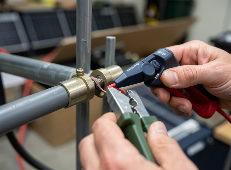
For PV-side MC4 contacts I use a ratcheting crimper with the correct MC4 die — the ratchet will not release until the crimp is fully formed, which removes the single biggest variable from the job: human inconsistency. For battery-side lugs from about 2 AWG up to 4/0, a hydraulic crimper is the honest tool. It develops the tonnage to make a full hexagonal or indent crimp on a thick-walled lug, where a hand tool simply cannot. A good ratcheting crimper for the small stuff and a modest 16-ton hydraulic crimper for the big stuff will outlast every cell you ever buy. As an Amazon Associate I earn from qualifying purchases. If you are assembling a kit, a hydraulic battery lug crimper kit is the one tool I would not let a beginner skip.
Round out the kit with a proper wire stripper sized for the gauges you run, a heat gun (not a lighter) for adhesive-lined heat-shrink, a torque wrench or torque screwdriver for the bolted terminations, and a clamp meter that reads DC current. The clamp meter is what closes the loop — it lets you confirm under real load that the connection you just made is carrying current without dropping voltage. Tools that take guesswork out of a high-current joint are not an indulgence; they are the cheapest insurance in the build.
Building the Connector Layer in the Right Order
There is a sequence that saves rework, and I follow it every time. First, lay out the full DC path on paper and pick the gauge for each segment from the ampacity it must carry — PV string, controller output, battery interconnect, inverter feed. Each segment has a different current and therefore a different conductor and lug size. Guessing one wrong here means re-crimping later.
Second, cut to length with a real service loop at every termination so a lug can be re-dressed without re-pulling cable, then strip, crimp, and immediately seal each joint with adhesive-lined heat-shrink before you forget which ones are done. Third, dry-fit everything — route the cables, set the glands, and confirm nothing is under tension — before you torque a single battery bolt. Fourth, torque the bolted terminations to the lug or busbar spec and mark each one with a paint pen so a glance tells you it has been checked.
Only then do you energize, and you energize in stages: bank to fuse to disconnect, then disconnect to inverter, watching for any junction that warms. The first time my workshop welder fired on the inverter, I had a clamp meter on the battery leads and a hand on each lug — that is how you commission a high-current DC system, not by closing the breaker and hoping. Doing it in this order means the expensive mistakes get caught while they are still cheap.
The Connector Mistakes That Cost the Most
After years of building and re-building, the failures cluster into a short list, and almost all of them are connector-layer problems rather than cell or inverter problems. The under-crimped lug tops the list — it is invisible until current flows, and it fails at exactly the moment of peak load. Right behind it is the mismatched or counterfeit MC4 pair, which seals beautifully and runs hot. Then the loose bolted terminal that was never torqued or that loosened from a cable under strain because nobody fitted a gland.
Bare copper left to corrode in a damp enclosure is the slow one — it does not fail this year, it fails in year four when the green crust has raised the joint resistance enough to matter. Undersized cable terminated with an oversized lug, or the reverse, gives a crimp that never fully compresses. And the quietest of all: a dozen merely-adequate connections, each dropping 20–40 mV, that together steal a noticeable slice of every day’s harvest without any single one being obviously bad. None of these are exotic. Every one is preventable with the right tool, the right part, and a meter to confirm the result.
How the Connector Layer Fits the Whole System
None of this lives in isolation. The connector you crimp feeds a BMS that has its own wiring discipline — covered in the BMS selection and wiring guide — and bolts onto busbars torqued to spec, which I detail in the busbar torque guide. The whole bank-to-inverter chain, and how the charge controller, panels, and inverter tie together, is mapped in my solar-battery integration overview and the wiring safety guide.
On the inverter end, surge behavior is what actually stresses these connections — a high inrush load tugs hard current through every junction at once. If you are still selecting that side of the system, my hybrid inverter guide and the EG4 18kPV review frame the surge-first thinking that decides which connectors you will be pushing the hardest. The same Home Assistant rule engine that watches my bank’s state-of-charge also flags any junction that starts trending warm — one dashboard for everything that matters.
Frequently Asked Questions
Can I mix MC4 connectors from different brands?
No. A connector that looks like an MC4 may use different contact geometry and copper alloy. Mating two brands makes a junction that passes a continuity check but runs hot under real current. Use matched pairs from one reputable manufacturer and crimp with the die that fits that contact.
What size cable do I need between my battery and inverter?
That is an ampacity question driven by your inverter’s maximum DC current and the run length, not by the connector. Size for continuous current plus voltage-drop margin, then pick a lug and connector rated above that. The full gauge math is in my battery wire sizing and ampacity guide.
Is welding cable safe to use for solar battery wiring?
It can be for indoor battery interconnects where its flexibility helps, but most welding cable lacks the UV rating and code listing for outdoor or PV-side use, and its fine strands must be properly tinned or lugged. For exposed runs, use PV wire or listed battery cable instead.
Why does my connector get warm but the cable stays cool?
A warm connector on a cool cable means the junction resistance is higher than the conductor’s. That is almost always a poor crimp, a corroded contact, or a mismatched connector. Measure the millivolt drop across it under load; replace or re-terminate rather than leaving it to run hotter as current climbs.
Do I really need tinned copper lugs, or is bare copper fine?
Bare copper works on day one and slowly oxidizes, raising resistance and heat over years, faster in humid, salty, or battery-vented air. Tinned lugs and adhesive-lined heat-shrink cost little and keep the joint low-resistance for a decade. In any enclosure or vehicle, tinned is the right default.
How much voltage drop across a connector is acceptable?
Aim to keep each individual connection well under about 1 percent of system voltage at full load, and treat any junction noticeably hotter or higher-drop than its neighbors as a defect. Measure the drop under real current with a meter; a cold continuity check hides high-resistance joints.
Related Guides
- MC4 Connectors Explained: Crimping, Sealing, and the Counterfeit Problem
- Anderson SB and PowerPole Connectors: Where Each One Belongs
- How to Crimp Battery and Solar Lugs Without a Cold Joint
- Choosing Solar PV Wire vs Welding Cable for DC Runs
- Cable Glands and Strain Relief for a Clean Battery Enclosure
- Heat-Shrink, Tinning, and Why Bare Copper Corrodes in a DC Bank
- DC Connector Voltage Drop: Measuring It Before It Costs You Watt-Hours