Important Disclaimer
BatteryStorageHQ provides educational content and estimates only. We are not certified installers, financial advisors, or electricians. Always consult with licensed professionals.
A hybrid inverter setup is the act of wiring one box to four energy sources at once — solar, battery, grid, and often a generator — and then programming the priority order it draws and pushes power between them. Get the wiring margins and the charge profile right and it runs for years untouched; get the LFP absorption voltage or the surge headroom wrong and you find out the first time the workshop fires up. On my bench a correctly commissioned 16S system holds cell drift under 20 mV at the top of charge, and that number is the difference between a quiet bank and a nuisance-tripping one.
I build LiFePO4 banks from bare prismatic cells here in Sweden, top-balance them, and run them through a hybrid inverter tuned by hand and watched in Home Assistant. This guide is the configuration layer — not which inverter to buy, but how to actually set one up so it behaves. If you still need to pick hardware, start with the best hybrid inverter roundup; everything below assumes the unit is already on the wall.
What a Hybrid Inverter Actually Does
A hybrid inverter is a single chassis that combines a battery inverter/charger, a solar charge controller (usually an MPPT), and a grid-interactive transfer system. It decides, moment to moment, whether to run the house from PV, from the battery, from the grid, or from a generator — and whether to send surplus solar back out. The honest framing is that you are not buying a battery; you are buying a traffic controller for electrons, and the setup is mostly about teaching it your priorities.
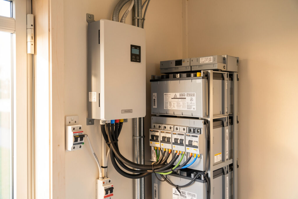
The four sources each connect to a dedicated terminal block: PV input (high-voltage DC string), battery (low-voltage DC, 48 V nominal on the units I run), grid/AC-in, and a load output that the inverter backs up during an outage. A generator, when present, lands on a second AC input or shares the grid terminal through a transfer relay. Understanding which terminal owns which job is the whole game — most first-time failures are a source landed on the wrong block, not a defective inverter.
Map Your Terminals Before You Touch a Wire
Before commissioning anything, label every terminal and confirm its rating. The battery terminal on a 5 kW class unit will pull well over 100 A continuous at 48 V, which dictates cable gauge and the Class-T fuse sizing on the main bank. The PV terminal has a maximum open-circuit voltage (Voc) ceiling that you must never exceed — and that ceiling is set by the coldest morning of the year, not the spec-sheet’s room-temperature number.
As an Amazon Associate I earn from qualifying purchases.
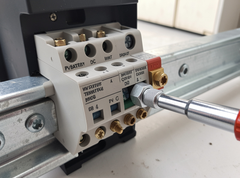
Here is the terminal map I work from on every install. It is the single sheet I tape inside the enclosure door, because six months later nobody remembers which lug fed the generator.
| Terminal | Source | Voltage class | Protection | Sets which spec |
|---|---|---|---|---|
| PV IN | Solar string | High-voltage DC (to ~500 V) | String fuse / DC breaker | Cold-weather Voc margin |
| BAT | Battery bank | 48 V nominal DC | Class-T fuse + breaker | Cable gauge, continuous A |
| GRID / AC-IN | Utility | 120/240 V AC | AC breaker | Pass-through current limit |
| GEN / AC2 | Generator | 120/240 V AC | AC breaker | Charge-current ceiling |
| LOAD / AC-OUT | Backed-up panel | 120/240 V AC | AC breaker | Continuous + surge rating |
Notice the last column. Each terminal forces a different sizing decision, and getting any one wrong cascades. Undersize the battery cable and you brown out under surge; overshoot the PV Voc and you can damage the MPPT on the first cold sunrise. I cover the cold-voltage trap in depth in the Voc rise in cold weather piece, because it is the wiring mistake I see most on northern installs.
The Configuration Stack: Six Layers, In Order
A hybrid inverter setup is not one setting — it is a stack of six configuration layers, and they have to be programmed in order because each depends on the one below it. Skip down the stack and you end up chasing ghosts: a charge fault that is really a battery-protocol mismatch, or an export fault that is really a grid-code setting. Here is the order I follow on every commission, and each layer has its own deep-dive spoke.
Layer 1 — Battery protocol and charge profile
Nothing else works until the inverter and the BMS agree. On a closed-loop system the inverter reads state-of-charge and per-cell data directly from the BMS over CAN or RS485; on an open-loop system you set the voltages manually and the inverter flies blind. For LFP I set absorption to roughly 3.45 V/cell (about 55.2 V on a 16S bank) and float low, around 3.375 V/cell (54 V), because holding LFP at a high float all day is how you cook calendar life for nothing. If you are still choosing or wiring the BMS, the BMS fundamentals guide and the DIY bank build cover the layer underneath this one.
Layer 2 — AC coupling vs DC coupling
How your solar connects fundamentally changes the wiring and the round-trip efficiency. DC-coupled solar runs through the hybrid’s internal MPPT straight into the battery; AC-coupled solar comes from a separate grid-tie inverter on the AC side. Most new DIY builds are DC-coupled and should be, but retrofits onto an existing string-inverter array are often AC-coupled — and the two behave very differently in an outage. I lay out the full tradeoff in AC coupling vs DC coupling explained.
Layer 3 — Split-phase and the 240V output
In North American homes the load output has to deliver 120/240 V split-phase, with two hot legs balanced around a neutral, or your 240 V dryer and well pump never run. Some units are natively split-phase; others need two stacked inverters or an autotransformer to synthesize the second leg. Getting the neutral-ground bond right in backup mode is a safety item, not a preference. The full wiring walk-through lives in split-phase 240V hybrid inverter setup, and the broader choice is covered in split phase vs single phase inverters.
Layer 4 — Grid interaction: sell, zero-export, or off-grid
Once the basics run, you tell the inverter what to do with surplus solar and how to treat the grid. Three modes cover almost everyone: grid-sell (push surplus back for credit), zero-export (use the grid but never feed it, often a utility requirement), and off-grid/island. Each is a handful of settings, and a wrong zero-export configuration can either trip your meter or quietly feed the grid when you are not allowed to. I walk all three in grid-sell and zero-export settings.
Layer 5 — Time-of-use and priority scheduling
This is where a hybrid earns its price. Time-of-use programming tells the bank when to charge from cheap grid power, when to hold for the expensive window, and when to favour solar. Done right it shifts your draw off the peak tariff without ever touching the inverter again. I cover the scheduling logic and the common own-goals in time-of-use programming for hybrid inverters.
Layer 6 — Generator input and AC charging
If you keep a generator for the winter gap, the inverter can start it, charge the bank from it, and pass its power to the loads — but only if the charge-current ceiling and the AC-input window are set so the generator is not stalled or hunting. This is the layer most people leave at defaults and regret. Full detail in generator input and AC charging, and the seasonal logic in generator backup for solar.
The LFP Charge Profile, Set Correctly
The charge profile is the setting people copy off a forum and get wrong most often. LiFePO4 is not lead-acid; it does not want a long absorption hold and it does not want a high float. On the bank I built, I set absorption to 55.2 V (3.45 V/cell) with a short absorption time or a tail-current cutoff, then drop float to 54.0 V (3.375 V/cell). That fills the cells to a genuine full without parking them at the knee of the voltage curve where calendar aging accelerates.
The single most important safety setting sits above the charger: the low-temperature charge cutoff. LFP must not be charged below freezing — plating lithium on a cold cell is permanent damage and a long-term safety risk. On a closed-loop system the BMS enforces this; on an open-loop inverter you may have to rely on the BMS alone, which is exactly why I never run a charge-only-from-inverter setup without a BMS that owns the temperature cutoff. The reasoning is laid out in the below-freezing charge cutoff and LFP cold-weather behaviour.
| Setting | Lead-acid habit (wrong for LFP) | Correct LFP value (16S/48V) | Why |
|---|---|---|---|
| Absorption voltage | ~58.8 V held for hours | 55.2 V, short or tail-current | LFP fills near the top knee fast |
| Float voltage | ~54–55 V continuous | 54.0 V or float disabled | High float ages cells for no capacity |
| Low-temp charge cutoff | Often ignored | Disable charge below 0 °C | Cold charging plates lithium, permanent |
| Charge current | 0.1C trickle | 0.3–0.5C is fine | LFP accepts charge fast and safely |
Sizing the Inverter to the Loads, Not the Array
The two near-universal sizing mistakes are oversized panels and an undersized inverter. People size the inverter to their average draw and then trip it the first time a deep-well pump or a compressor motor kicks. The spec that matters is surge — locked-rotor amps (LRA) on a motor can be five to seven times its running current for a fraction of a second, and a high-frequency inverter that brags about efficiency may fold the instant that happens.
Low-frequency (transformer-based) inverters like the Victron MultiPlus-II carry far more surge headroom than the lightweight high-frequency units, which is why I measure everything against the MultiPlus-II as a reliability benchmark. If your loads include a well pump, a workshop compressor, or a welder, size for the surge and treat the continuous rating as the easy part. The whole-home sizing method works the kW and kWh sides separately, which is the only honest way to do it.
Picking the Hardware Class That Matches Your Setup
Configuration is easier on some platforms than others, and the right unit depends on what you are wiring it to. The all-in-one low-frequency boxes — the EG4 and Sol-Ark class — bundle the MPPT, the split-phase output, and generator control in one chassis, which simplifies the stack above. The modular Victron approach gives you finer control and famous reliability but more boxes to configure. The budget Growatt SPF gets you running for less but with thinner surge margins and rougher closed-loop support.
I have run all three categories side by side. The decision usually comes down to whether you value integration or modularity, and I break it down in Sol-Ark vs EG4, the EG4 18kPV review, the Growatt SPF 5000 review, and the Schneider Conext XW Pro review. Whatever you land on, confirm it is a pure sine output under load — modified sine has no place near sensitive electronics, as I show in pure sine vs modified sine.
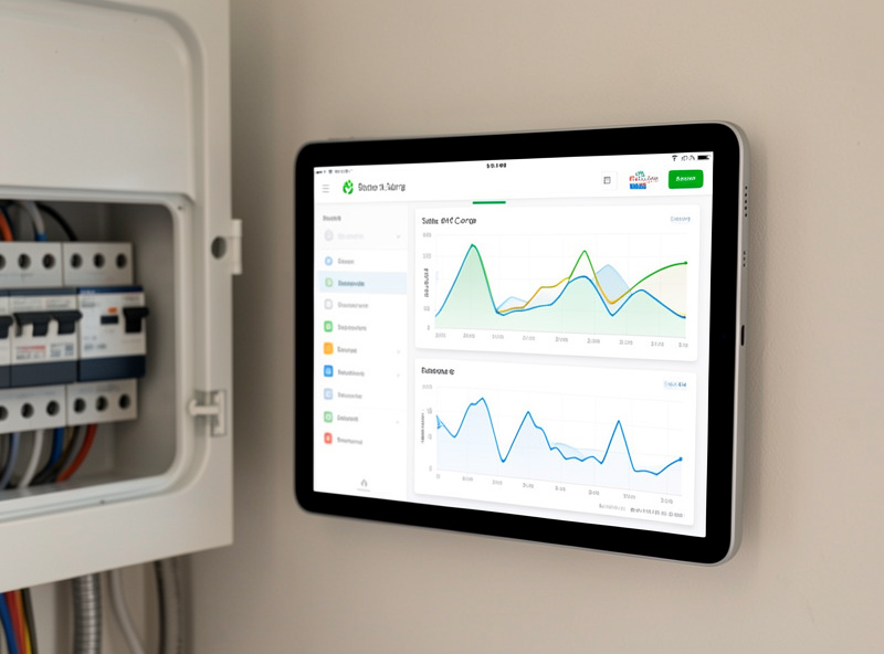
Monitoring: Close the Loop or Stay Blind
A hybrid inverter you cannot see into is a hybrid inverter you cannot trust. I run every system into Home Assistant over MQTT, reading per-cell voltage, state-of-charge, daily PV, and load — the same rule engine that watches the curing-chamber humidity and the hydro reservoir levels also watches battery SoC, so it is one dashboard for everything that matters. Closed-loop communication between the BMS and the inverter is worth chasing: it lets the inverter taper charge on a single lagging cell instead of bulk-charging into a BMS disconnect.
If you want the integration details — protocols, dongles, and the MQTT path — I wrote them up in smart inverter monitoring. The payoff is that you catch a drifting cell as a slow trend in the logs, weeks before it becomes a charge fault that drops your backup at the worst moment.
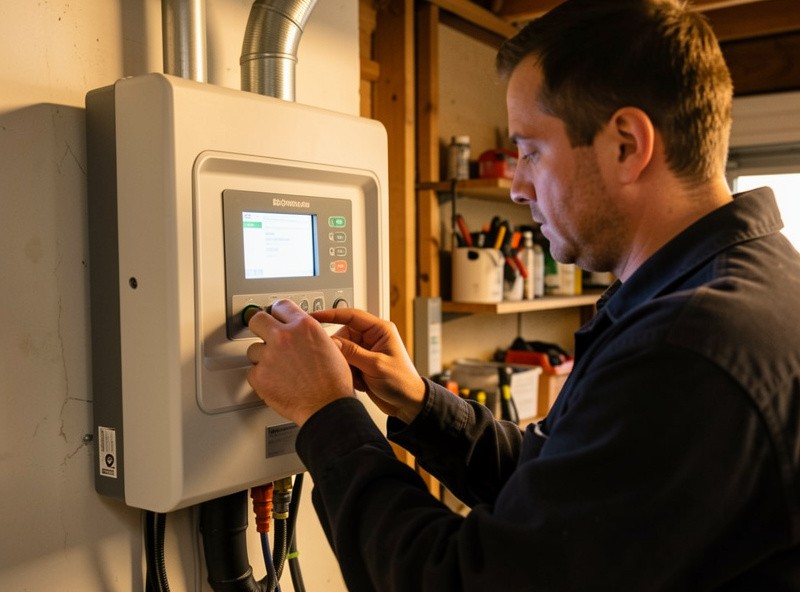
Commissioning: The Order of Operations That Avoids the Bang
Commissioning is where a careful build either comes alive quietly or announces itself with a spark. The order matters: verify polarity and torque every busbar to spec before any source is energized, bring the battery up first behind its fuse, confirm the inverter sees correct pack voltage, then energize PV, then connect grid, then test transfer, and only then add load. Each step has a measurable pass/fail — pack voltage within a volt of the BMS reading, no DC offset on the AC output, a clean transfer under 20 ms on the units that claim it.
I keep a written commissioning checklist and tick every line, because the failure modes here are the expensive ones. The full sequence — torque values, the order of energizing, what to measure at each step, and the first-power-up tests — is in commissioning a hybrid inverter system. If you are paralleling two or more units for more power or redundancy, that adds a synchronization layer on top, covered in paralleling hybrid inverters.
Where Hybrid Inverters Fit the Bigger System
The inverter is the hub, but it only behaves if the layers around it are right. The battery has to be a properly top-balanced, compression-fixtured bank — a job I cover end to end in top balancing LFP cells. The solar side has to be sized for your real winter, not a sunbelt brochure, which for northern installs means the winter-gap sizing math and an honest read of winter output collapse. And the way panels, charge control, and inverter tie together is its own subject, walked in solar and battery integration.
If your goal is whole-home backup rather than off-grid, the inverter pairs with a transfer switch and the planning in the home backup power guide. And if you are charging an EV off the same system, the priorities change again — that interaction is in EV charging from solar and batteries. The point is that “hybrid inverter setup” is never just the box; it is the box programmed to serve the system you actually built.
Setting Output and Charge Priority
Underneath the six layers sits a decision the inverter makes every second: which source feeds the loads, and which source charges the battery. Most hybrids expose this as two priority settings — load-source priority and charge-source priority — and the defaults are rarely what a solar-first home actually wants. On my system I set load priority to solar-then-battery-then-grid so the house runs on sun first, dips into the bank second, and only touches the grid when both are spent. That single ordering is what turns a grid-tied house into a genuinely solar-powered one during the day.
Charge priority is the mirror image and the place people quietly waste their panels. If charge priority is set to “solar and grid together” on a flat tariff it works fine, but on a time-of-use tariff it will pull expensive grid power to top the bank at noon when free solar is right there. I set charge priority to solar-only during daylight and let a scheduled grid-charge window handle the rest, which is exactly the logic the time-of-use programming guide builds out in detail. The two priority knobs interact with every other layer, so I set them last and then watch a full day in the logs before trusting them.
One subtlety that trips people: in an outage, an AC-coupled array behaves differently from a DC-coupled one because the hybrid has to throttle a separate grid-tie inverter using frequency-shift, while a DC-coupled array charges straight through the internal MPPT. If your priority settings seem to ignore solar during a blackout, the coupling type is usually the reason — another argument for reading the coupling comparison before you finalize the priority logic.
The Five Setup Mistakes I See Most
Across the inverters and BMS boards I have run, the failures cluster into the same handful of mistakes, and none of them are exotic. They are the boring, preventable ones that show up weeks after commissioning when the season changes or the workshop load shifts. Here is what I check for first whenever someone tells me their hybrid “isn’t working right.”
One — copying a lead-acid charge profile onto LFP. The high absorption hold and high float that suit flooded lead-acid slowly age lithium cells and can push a weak cell into BMS over-voltage on every cycle. Use the LFP numbers in the table above, not the inverter’s factory lead-acid preset.
Two — undersizing the inverter for surge. A 5 kW continuous rating means nothing if your well pump’s locked-rotor draw spikes past the surge ceiling. Size to the worst motor start, not the average watt-hours. The sizing method separates these two numbers deliberately.
Three — ignoring cold-weather Voc. A string that sits comfortably under the MPPT voltage ceiling on a warm afternoon can climb past it on a clear, sub-zero morning and damage the controller. Northern installs especially have to design the string length around the coldest expected temperature, as the Voc-rise piece spells out.
Four — leaving the neutral-ground bond wrong in backup mode. On a split-phase backup, the bond has to follow the source, or you get nuisance GFCI trips at best and a safety hazard at worst. The split-phase walk-through covers exactly where that bond belongs.
Five — running open-loop with no temperature cutoff. If the inverter charges on manual voltages and nothing owns the low-temperature cutoff, the system will happily charge a frozen bank. The BMS must hold that line; never delegate it to hope.
Frequently Asked Questions
In what order should I program a hybrid inverter?
Program from the battery up: first the battery protocol and LFP charge profile, then AC or DC coupling, then the split-phase output, then grid mode (sell or zero-export), then time-of-use scheduling, and last the generator input. Each layer depends on the one below it.
What absorption and float voltage should I set for a 16S LiFePO4 bank?
On a 48V 16S LFP bank I set absorption to about 55.2V (3.45V per cell) with a short hold or tail-current cutoff, and float low at around 54.0V (3.375V per cell). High lead-acid float voltages held all day age LFP cells for no extra capacity.
Do I need closed-loop communication between the BMS and inverter?
It is not strictly required, but it is worth chasing. Closed-loop lets the inverter read per-cell data and taper charge on a single lagging cell instead of bulk-charging into a BMS disconnect. Open-loop works but flies blind on voltages you set manually.
Should I size a hybrid inverter to my solar array or my loads?
To your loads, specifically the surge. Motor loads like well pumps and compressors draw five to seven times their running current for a fraction of a second. Size for that locked-rotor surge and the continuous rating takes care of itself.
Is AC coupling or DC coupling better for a hybrid inverter?
For new DIY builds, DC coupling through the hybrid’s internal MPPT is usually simpler and more efficient. AC coupling makes sense when retrofitting onto an existing string-inverter array. They behave differently in an outage, so the choice changes your wiring.
Can I charge my LiFePO4 bank below freezing through the inverter?
No. Charging LFP below 0 degrees Celsius plates lithium and causes permanent damage. Set a low-temperature charge cutoff so charging stops below freezing, and rely on a BMS that owns that cutoff rather than the inverter alone.